Robot Inversion Installation Device
House of Design is an up and coming company which develops manufacturing lines utilizing robots for a wide range of innovative work. The company must often lift and mount robot arms weighing anywhere from 50-3000 lbs on shelves, walls, ceilings, and all angles between which can require the assistance of several employees. This can be extremely dangerous and time-consuming. The purpose of this project is to develop an installation device that would accommodate the lifting and rotation of a robot up to 180 degrees to mount at any angle the company could ever need. Therefore, a product is to be designed to help House of Design perform its daily tasks with increased safety and efficiency.

The Team

Members
- Chris Barba
- Trevor Rush
- Nathan Sheehan
- Amanda White

Robot Inversion Installation Device

Robot Inversion Installation Device
Problem Statement
House of Design is a company which develops manufacturing lines utilizing robots. The company must often lift and mount robot arms weighing up to 3000 lbs on walls and ceilings which can require the assistance of several employees. This can be very dangerous and time consuming. The purpose of the project is to develop a machine or tool that would accommodate the lifting and rotation of a robot up to 180 degrees so it may be mounted. Therefore, a product is to be designed so that it will be safe as well as help House of Design perform its daily tasks.
Standards and Regulations
OSHA Standards
1. 1910.212
- Types of guarding. One or more methods of machine guarding shall be provided to protect the operator and other employees in the machine area from hazards such as those created by point of operation, in going nip points, rotating parts, flying chips and sparks. Examples of guarding methods are-barrier guards, two-hand tripping devices, electronic safety devices, etc.
2. Section 5(a)(1)
-
- “General Duty Clause” – how product is related to an employer’s responsibility for occupational safety and health.
3. 1910.178(a)(5)
-
- If the truck is equipped with front-end attachments other than factory-installed attachments, the user shall request that the truck be marked to identify the attachments and show the approximate weight of the truck and attachment combination at maximum elevation with load laterally centered.
Benchmarking
Drum Grab
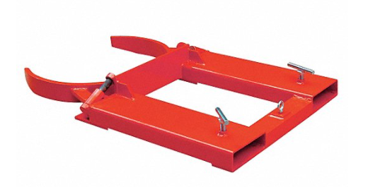
Pros:
-
Load Capacity: 1500 lbs.
-
Material: Steel
Cons:
-
Weight: 114 lbs.
-
Fork Pocket Size: 5-1/2″ x 2″
-
Requires drum to have indents to grip around and avoid slipping
Summary:
A good example of a standard drum grab used for picking up barrels for transportation. This design could be inspirational for adjusting the forks in a forklift to hold the robot arm.
Source:
Forklift Rotator Attachment
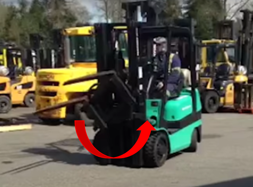
Pros:
-
A purchasable attachment for forklifts
-
Replaceable ring-bearing insert
-
Safety locks on side of forks
-
Smooth 360 degree continuous motion
-
Load Capacity: 3200-7000 lbs.
Cons:
-
Does not include a top grip/third arm
-
No rounded fork attachment
Summary:
This is a good example of an existing system that lifts and rotates 360 degrees and is also an attachment to standard forklifts.
Source:
Hydraulic Drum Dumper
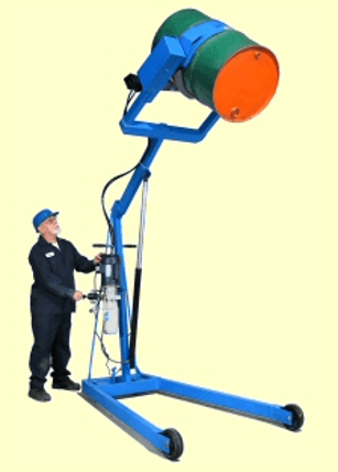
Pros:
-
Strap tightens around body of drum
-
Lift Capacity: 8 ft.
-
Load Capacity: 800 lbs.
-
Rotates 360 degrees
-
Does not require forklift
Cons:
-
Potential problems with rotating the robot arm if fully extended
-
Requires more manufacturing
Summary:
This is an interesting design for an alternative to adapting and utilizing a forklift. With this design there is more visibility for the operator but more complex to use.
Source:
https://morsedrum.com/products/400_Hydra-Lift_Drum_Karriers.htm
Turnaload
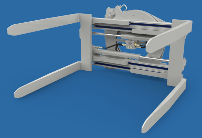
Pros:
-
Efficient hydraulic system which maximizes energy consumption
-
Clamp and backhand protection
-
Flow divider for equal arm movement
Cons:
-
Requires access to forklift
-
May not grip irregular/cylindrical shapes well
Summary:
Design allows for both sets of forks to clamp down on items and rotate them around.
Source:
Background and Problem Analysis
Customer Provided Constraints
-
$2000 Prototyping Budget
-
ABB Robot Weight Range: 100-1000 lbs
-
Must be able to vertically rotate and lift robots to be mounted on walls and ceilings
-
Meet OSHA Standards
-
Ideally 3 or less people required for operation
Customer Provided Requests
1. Optional usage of forklift
2. Constructed of carbon steel
3. Rotate vertically and mount at any angle between 0° to 180°
4. Compatible with other robots manufacturers
5. Be marketable
6. Operate in limited installation space
7. Optional hand cranking for rotation
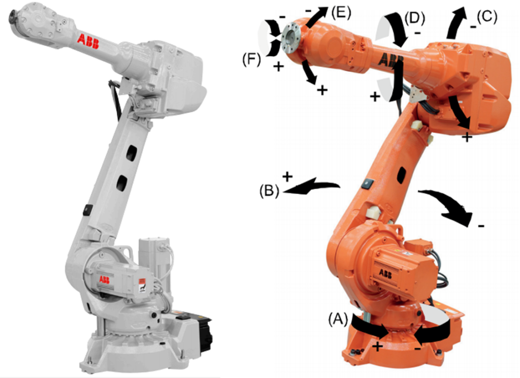
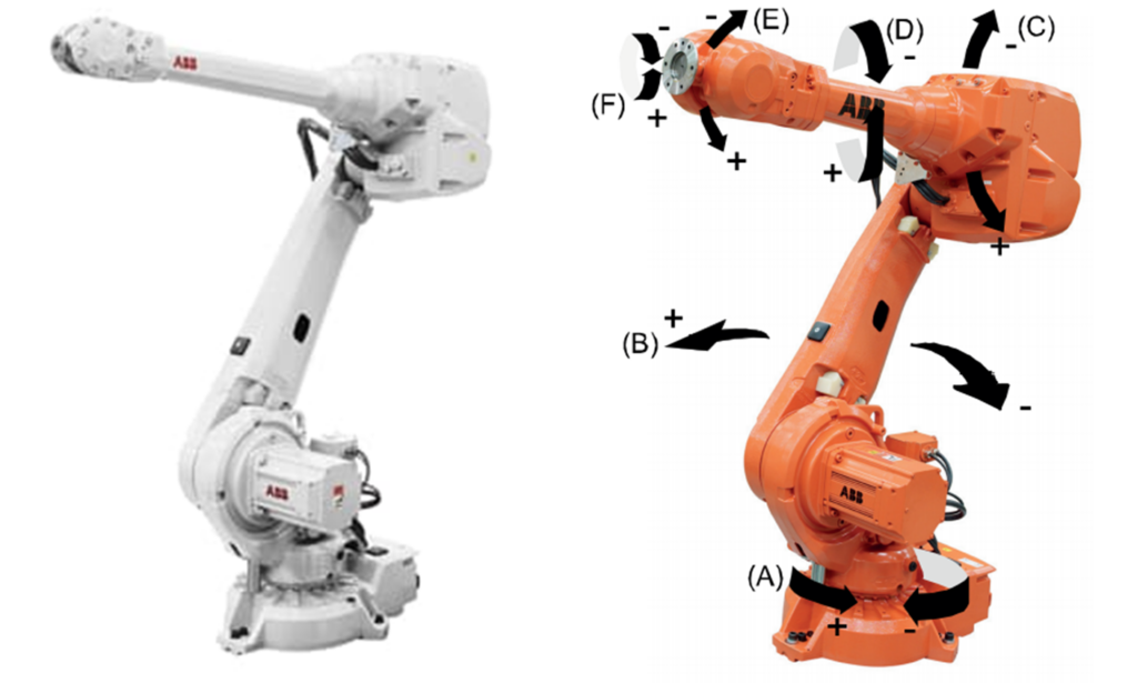
ABB ROBOTS OF INTEREST
IRB 1200
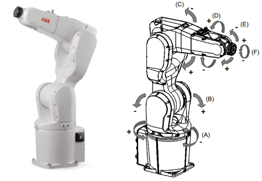
Overall Weight: 54 kg (120 lbs)
Robot’s Potential Mounting Positions: Any angle
IRB 1300
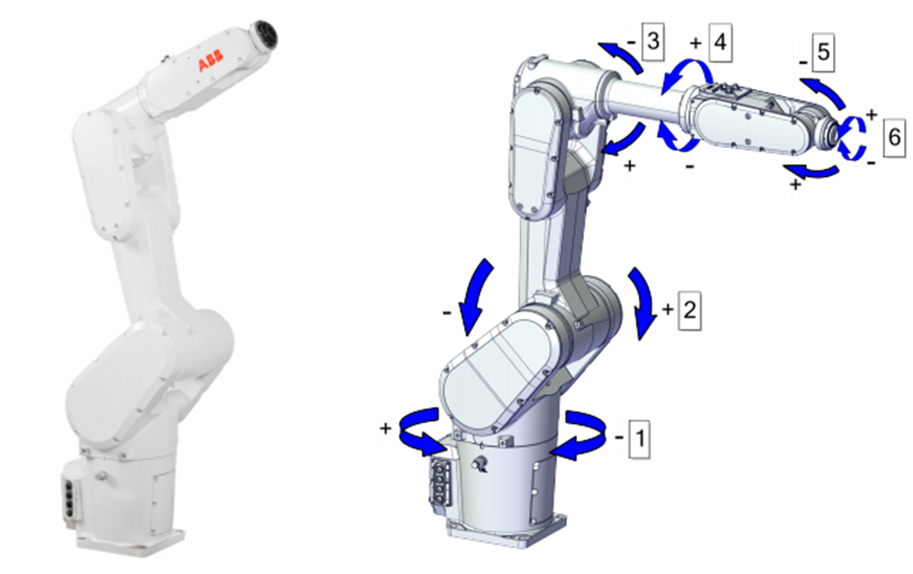
Overall Weight: 78 kg (172 lbs)
Robot’s Potential Mounting Positions: Any angle
IRB 1600
Overall Weight: 250 kg (551 lbs)
Robot’s Potential Mounting Positions
- Floor
- Shelf
- Tilted
- Wall
- Inverted
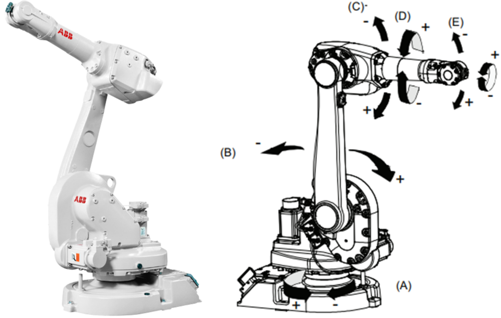
IRB 2400
Overall Weight: 380 kg (838 lbs)
Robot’s Potential Mounting Positions:
- Floor
- Wall
- Inverted
IRB 2600
Overall Weight: 272-280kg (600-617 lbs)
Robot’s Potential Mounting Positions:
- Floor
- Shelf
- Tilted
- Wall
- Inverted
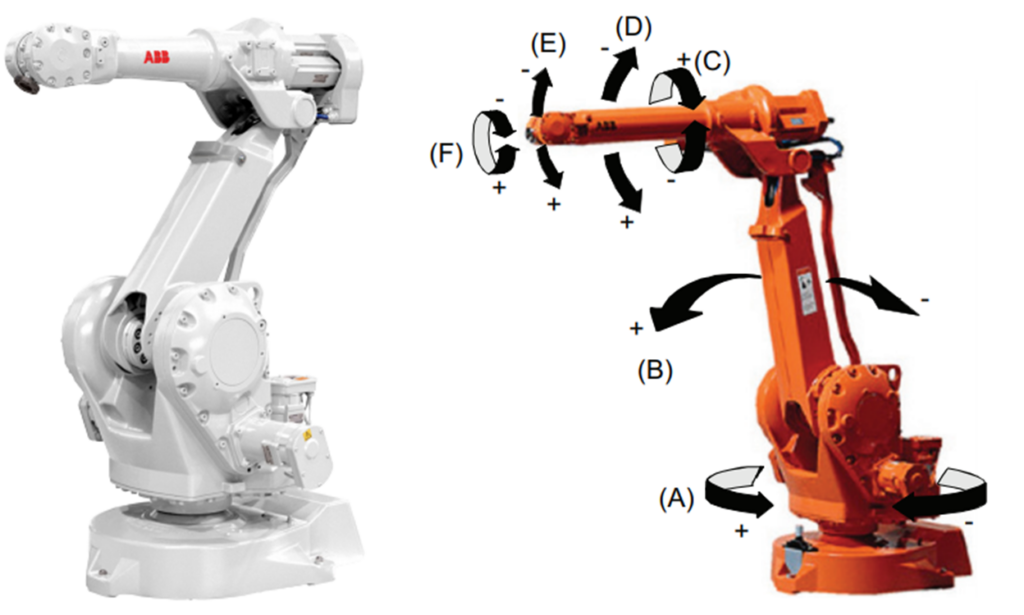
IRB 4600
Overall Weight: 425 kg (936 lbs)
Robot’s Potential Mounting Positions:
- Floor
- Shelf
- Tilted
- Inverted
Needs
| Need # | Description of Need | Justification | Required Y/N |
|---|---|---|---|
| 1 | Safely Operable | Background and Problem Analysis Constraint 4 | Y |
| 2 | Minimize crew needed for installation | Background and Problem Analysis Constraint 5 | Y |
| 3 | Able to elevate robot off ground
|
Background and Problem Analysis Constraint 3 | Y |
| 4 | Vertically Rotate Robots up to wall and ceiling | Background and Problem Analysis Constraint 3 | Y |
| 5 | Able to accommodate a variety of sizes and models | Background and Problem Analysis Constraint 2 | Y |
| 6 | Operate in limited installation space | Background and Problem Analysis Request 6 | N |
| 7 | Have lifetime equal or greater than the time needed to gain ROI | Product Effectiveness | N |
| 8 | Marketable | Background and Problem Analysis Request 5 | N |
Specifications
| Spec. Item | Related Need # | Specification | Justification and Reference | Required Y/N |
|---|---|---|---|---|
| A | 1 | Conform to OSHA Standards | Standards and Regulations 1 and 2 | Y |
| B | 4 | Rotate robot and mount on wall or ceiling | Background and Problem Analysis Constraint 3 | Y |
| C | 3, 5 | Able to lift and support ABB robot of weights varying from 100 lbs to 1000 lbs | Background and Problem Analysis Constraint 2 |
Y |
| D | 2, 6 | Ideally require 3 or less persons for mounting of robot | Background and Problem Analysis Constraint 5 | Y |
| E | 8 | Prototype must be manufactured for less than $2000 | Background and Problem Analysis Constraint 1 | Y |
| F | 4 | Can assist in mounting at various positions between 0° and 180° | Background and Problem Analysis Request 3 |
N |
| G | 5 | Potentially compatible with robots of different manufacturers within similar weight range | Background and Problem Analysis Request 4 |
N |
| H | 7 | Fabricated from carbon steel | Background and Problem Analysis Request 2 | N |
| I | 8 | Be aesthetically comparable to robot | Background and Problem Analysis Request 5 | N |
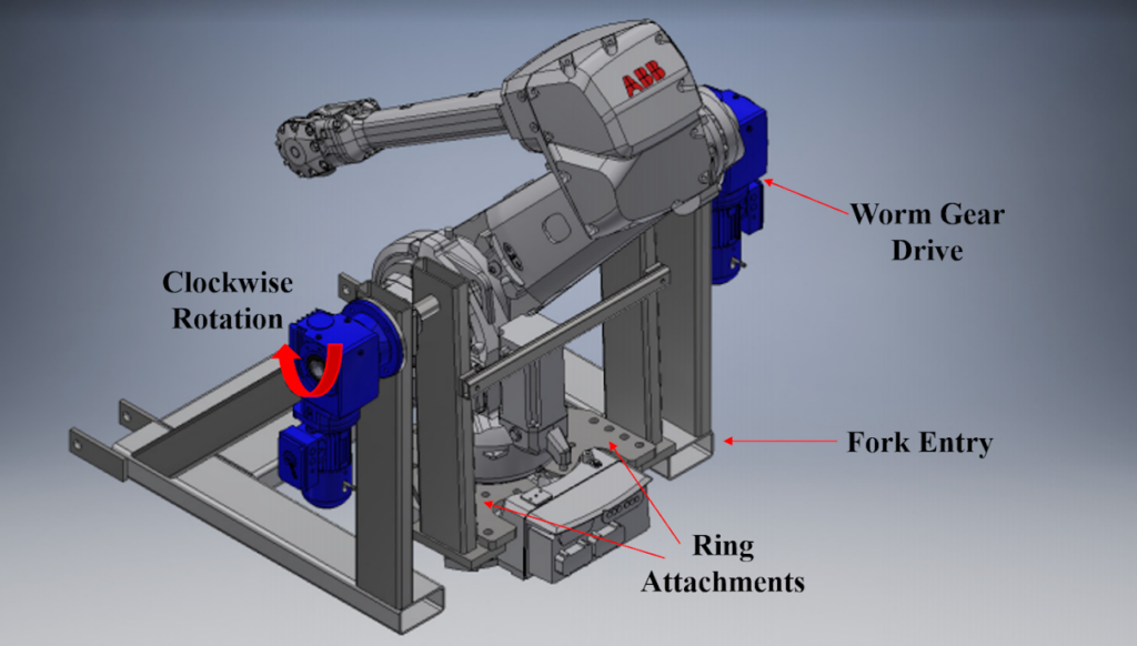
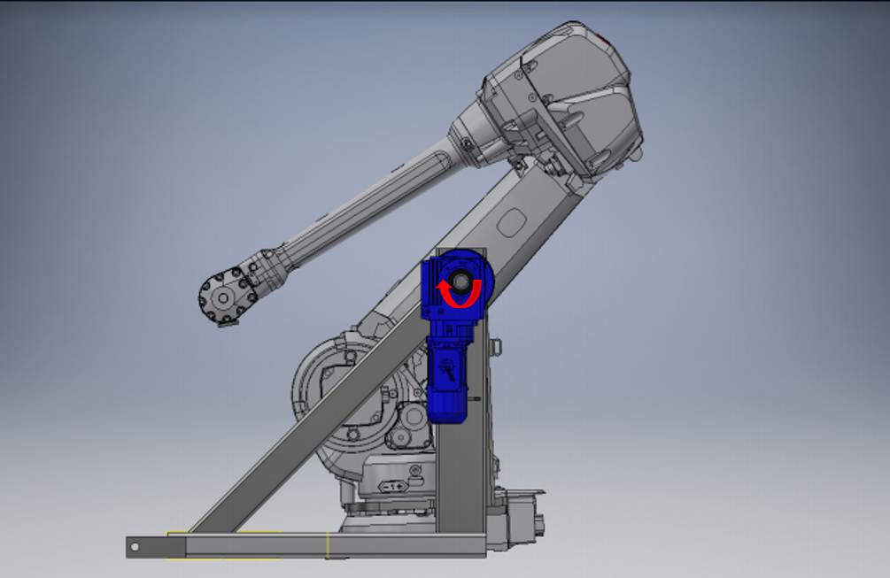
Form and Function
Goal Operating Procedure
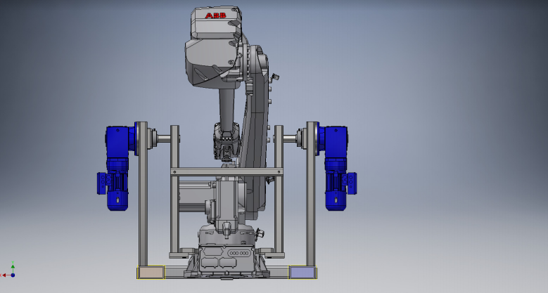
The ABB robot will be lifted a few inches off the ground via fork lift. It will then be moved into place in the inverter drop cage assembly where the robot specific ring attachment will be bolted to the attachment holes. Once the robot is secure in the cage assembly, a forklift will insert its forks on the gear motor side of the assembly. The robot will then be lifted off the ground and then rotated anywhere between 0 and 180 degrees using the worm gear drives simultaneously. At the desired angle of mounting, the gear drives will hold the robot in place while an engineer bolts the robot down. The ring attachment will then be released from the assembly and the cage can be removed from the robot.
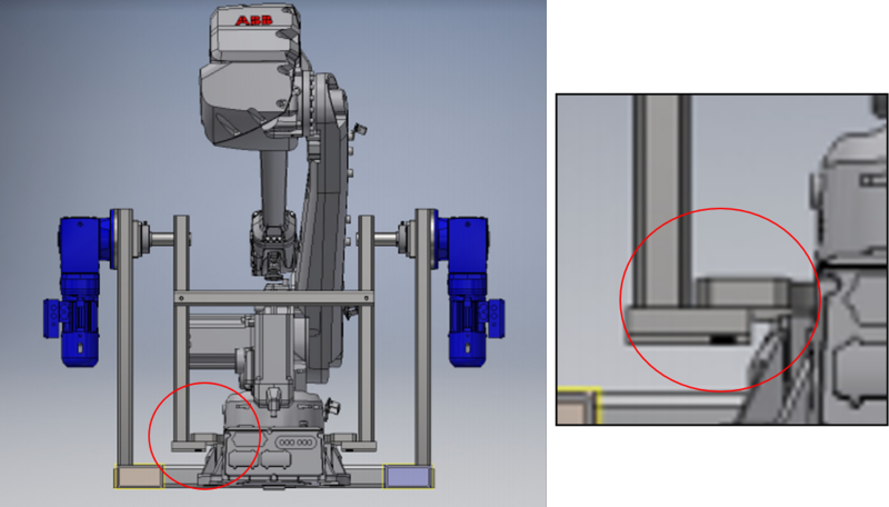
Cage Assembly
Analysis of Performance
Aspects to Analyze
-
Conforms to OSHA standards
-
The time required for each robot to be safely inverted from the ground to the ceiling
-
Longevity of structure
-
Exactness of rotation
-
Effectiveness of locking/blocking mechanisms
-
Ability to work with robots of different sizes
Testing of Performance
Testing will focus on the most critical parts of the assembly where calculations show failure is most likely to occur.
Testing Apparatus

The images above represent the torsional force acting on the feet of the drop cage. One end of a vertical shaft will be welded on to the end of the ‘foot’ while a force acts on the other in order to replicate torsion on the drop cage leg. This will test the welds on the end of the drop leg shaft to the feet. Engineers will then compare testing results to paper calculations and finite element analysis.
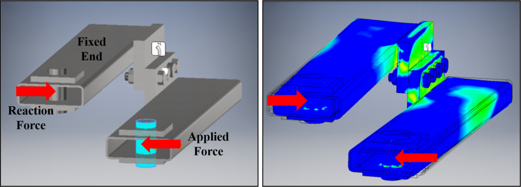
The images above represent the torsional and shear forces acting on the drop cage ‘foot’ weld and bolts. Shafts will be welded on to the drop cage ‘feet’ connected via SAE grade 8 bolts. Forces will then push the two shafts toward another to represent the torsional stress acting between the drop cage ‘feet’ and the ring attachments. Engineers will then compare the testing results to paper calculations and finite element analysis.