Teaching Robots to Walk
Our goal as team ACRO is to design, develop, and test a high-performance configurable acrobat style robot for controls algorithm development and demonstration. While using novel methods to ensure a unique and interesting design is achieved, we will meet professional manufacturing standards and the unique needs of the Boise State Robotics Lab. Understanding how to control this style of underactuated robot is one of the building blocks to more advanced walking robots.
The Team
Members
- Nicholas Blancett
- Chris Goodwin
- Lyndee Manning
- Chris Ray
- Joel Velazquez
Teaching Robots to Walk
Acro-Bot Design Project
Executive Summary
Dr. Satici requires an acrobot for machine learning testing. The goal is to develop a design which is uniquely suited to the robotics lab’s requirements. First, the standards and regulations section covers the OSHA standards relevant to this project, all of which are tied to the safety of the user. After this, the benchmarking section covers the 4 chosen benchmarks for this project; the existing BSU model, inertia wheel pendulum, Kendall Lui acrobot, and the irb 1520id.
Each benchmark brings a specific quality to base our design off of, which leads to the background and problem analysis lays out all the constraints and suggestions from Dr. Satici, including the project budget. This all helps create the stakeholder analysis, which defines who this project affects, and how. This informs our design decisions, which are seen in the needs section. Here, the essential elements for a successful design are introduced. First and foremost safety is covered. For example, the number one need listed is a safety switch. Lastly, the specification section lays out the requirements for the success of the project.
Problem Statement
Dr. Satici of the Boise State Robotics Lab, requires an acrobot for machine learning testing. While there is a wealth of designs on the market already, the goal is to use novel methods to develop a design which is uniquely suited to the robotics lab’s requirements, while maintaining professional standards of manufacturing.
Standards and Regulations
OSHA Standard 29 CFR 1910.179(a)(59) defines “emergency stop switch” as a manually or automatically operated electric switch to cut off electric power independently of the regular operating controls.
OSHA Standard 1910.147 and subsequent reference NIOSH publication 94-110 determine the lifting capabilities of individuals.
Benchmarking
BSU Existing Model
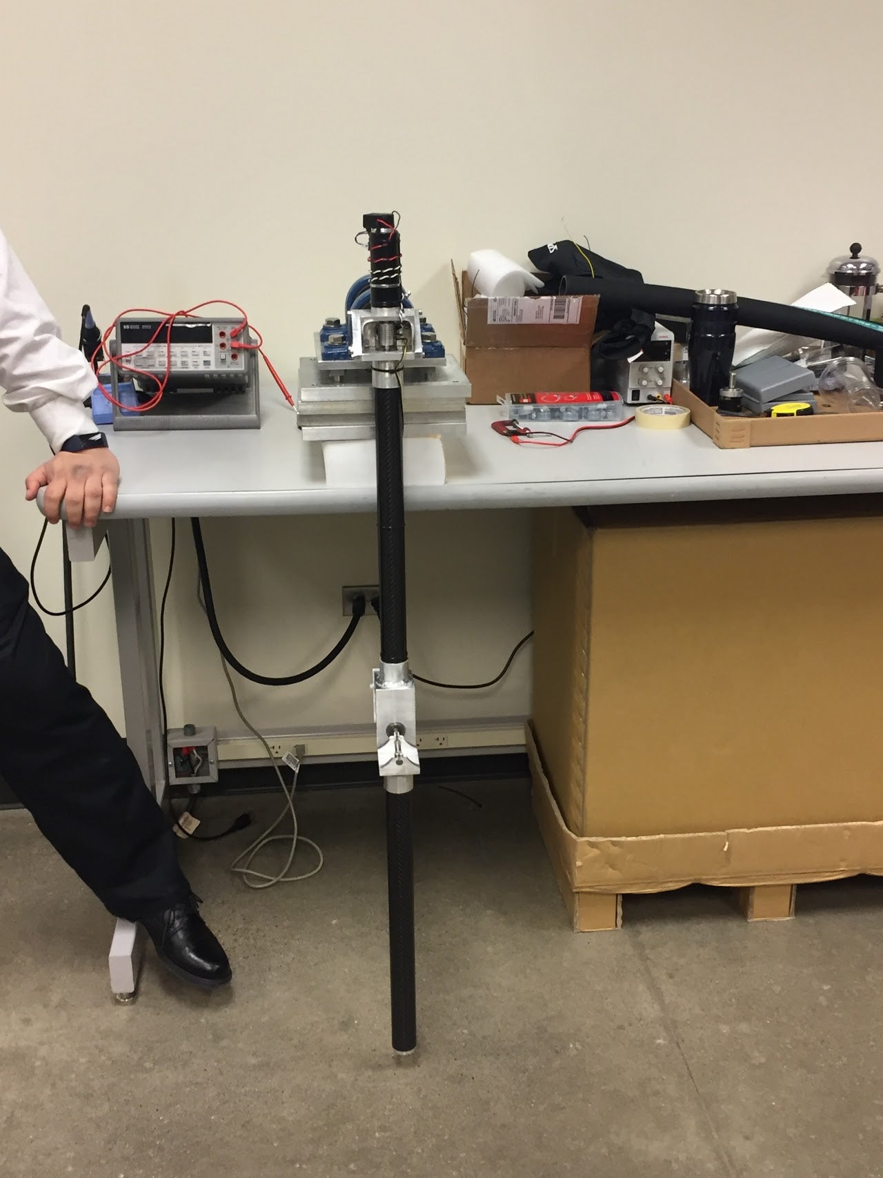
Pros
- Simple design
- Motor location counterbalances arms reducing required power
Cons
- Non-Professional Design
- Size of arms cause safety risk
- Carbon fiber pendulum arms prevent disassembly for maintenance/repair.
- Poor bearing selection.
Conclusion
The existing BSU model has a simple design. The motor was located on the top of non-driven pendulum acting as a counterbalance to reduce the required operating power. However, the design was not professional. The arms were very large causing a safety risk to the user. The use of carbon fiber arms made the device impossible to disassembly for maintenance. Lastly, the current main shaft bearings were designed for low speed high load uses, which causes high friction losses.
Inertia Wheel Pendulum
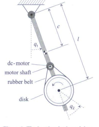
Pros
- Motion predictable
- Weight easily adjustable
- Center of gravity in the center of the wheel
- Capable of Large Velocities
- Durable
- Simple
Cons
- High Friction
- Flexibility of belt leading to a coupling effect
- Dead Zone
- Awkward motor mounting position
- Open belt is not aesthetically pleasing
- Safety
Conclusion
The inertia wheel pendulum is our second solution. This is a model created by Taylor and Francis. The design is fairly simple. A disk is attached at the end of a pendulum and belt driven by a motor mount slightly above it. This design makes the motion of the pendulum relatively easy to predict and its simplicity should make the system fairly durable. However, the open nature of the belt raises safety concerns and this method produces high levels of friction in the bearings and belt.
Kendall Lui Acrobot
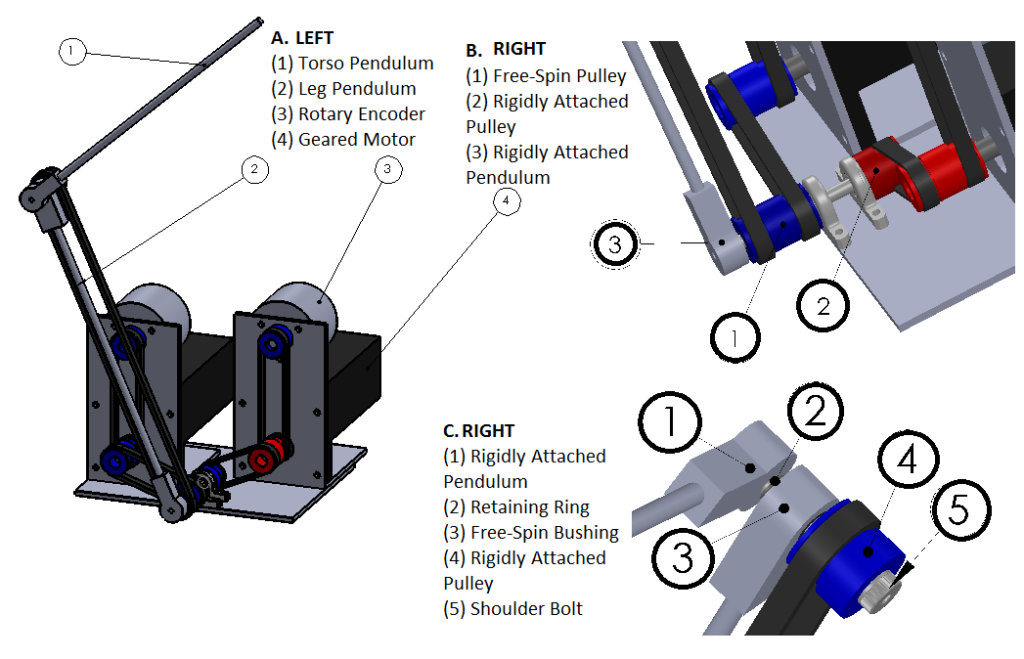
Pros
- Simple Pendulum
- Cost similar to our budget
- Alternate drive method
Cons
- Exposed belt is a safety risk
- Complicated drive system
- Cart mounted
Conclusion
The Kendall Lui model of the acrobot shows a simple pendulum design that is on point with the customers budget. The system is dual belt-driven. This is an alternate drive method to the current model at Boise State. However, the belt is exposed, causing a safety risk for the users. Additionally, the dual belt drive is complicated and the device is cart mounted. Both of these factors are outside the scope of this project.
IRB 1520ID
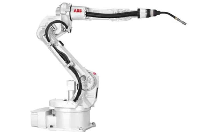
Pros
- Professional robotics aesthetics
Cons
- Extremely expensive relative to the project budget.
Conclusion
The IRB 1520ID is an example of professional-level aesthetics giving a benchmark to base future design aesthetics off of.
Background and Problem Analysis
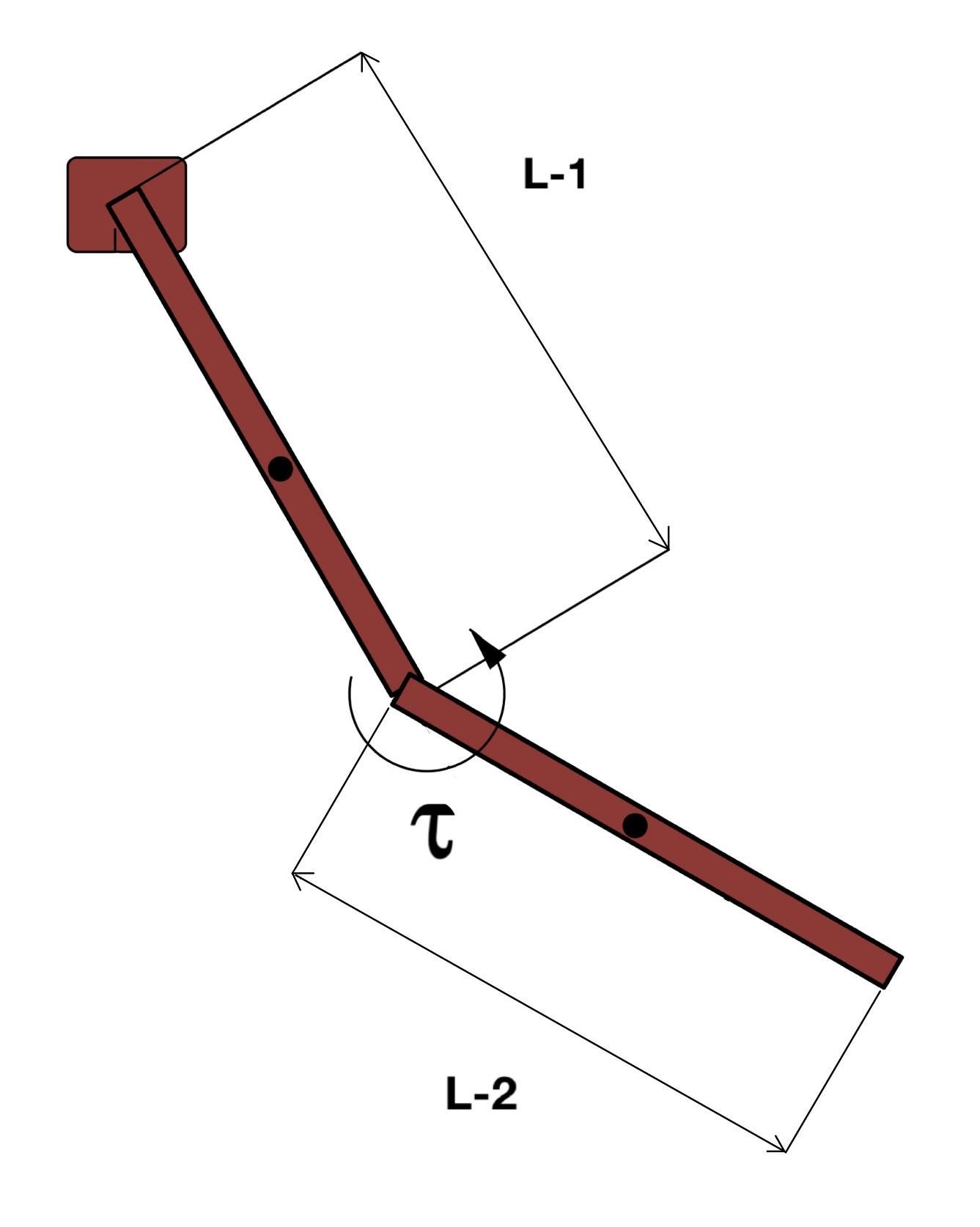
Table 1 Dr. Satici Constraints:
| Item No. | Item: | Value: | Justification: |
|---|---|---|---|
| 1 | Must include safety shutoff | N/A | Dr. Satici Requested an emergency shutoff |
| 2 | Smaller total length | <70 cm | Dr. Satici said he wants a device smaller than the existing BSU model. |
| 3 | Mount shaft Diameter | < 1.5” | Dr. Satici said the mount shaft diameter on the BSU existing model was too large. |
| 4 | Encoder ticks: | 2048 ticks/revolution | Dr. Satici said we must use encoders with that resolution or higher. |
| 5 | Should include provisions for inertia wheel | N/A | Requested by Dr. Satici. |
| 6 | Device must include provisions for secure mounting to a table | standard size | Requested by Dr. Satici. |
| 7 | Easily Serviceable | N/A | Requested by Dr. Satici |
| 8 | 2nd link must be driven | N/A | Definition of Acrobot |
| 9 | Must be man portable | N/A | Dr.Satici requires the device to be able to be moved from place to place. |
| 10 | Within Budget | $800 | Dr. Satici set the budget of the project to $800 dollars. |
| 11 | Professional aesthetics | N/A | Dr. Satici requested a professional appearance, especially with concern to wiring. |
Table 2 Customer Suggestion:
| Item No. | Item: | Value: | Justification: |
|---|---|---|---|
| 1 | Use of current motor | Continuous torque: 0.138 lbf-ft
Stall Torque: 1.888 lbf-ft |
Dr. Satici suggested the use of the motor from the existing BSU model. |
| 2 | Use of current encoders | 2048 ticks/revolution | Dr. Satici suggested the use of the encoders from the existing BSU model. |
.
Stakeholder Analysis
Operators
- Safety
- Ease of use for user and system interface
- Easily controllable through supplied systems
- Precision
- Portability
Maintenance Crew
- Low maintenance or long life
- Maintenance time/required skill
- Widely available parts
Boise State University Robotics Lab
- Desired Performance
- Marketability
- Cost
Manufacturing Company
- Ease of production
- Cost of production
Needs
| Need #: | Description of Need: | Justification: | Required Y/N: |
|---|---|---|---|
| 1 | Must have a safety switch located well away from the primary mechanism. | Background and problem analysis: 1.1, Key for operator safety, OSHA Standard 29 CFR 1910.179(a)(59) | Y |
| 2 | The device must mount securely to a table or be self contained. | Background and problem analysis: 1.6 Key for operator safety. | Y |
| 3 | The second link must be driven | Problem definition and Background and problem analysis 1.8. | Y |
| 4 | Must have accurate position measurements. | Background and problem analysis: 1.3 & 2.2, This is a controls testbed. If it can’t tell where it is, it can’t be controlled
Customer Constraint. |
Y |
| 5 | Replaceable second pendulum with inertia wheel | Background and problem analysis: 1.5 | Y |
| 6 | The fully stowed device must be portable by a single person with no special equipment | Background and problem analysis: 1.9 | Y |
| 7 | Reasonable cost/within budget | Customer Constraint based on cost of existing BSU model. | Y |
| 8 | Must be readily serviceable by client with common hand tools (Allen wrenches, pliers, Phillips head screwdriver) | Background and problem analysis: 1.7 | Y |
| 9 | Professional Aesthetics (I.E clean wire runs, covered joints/pinch points.) | The customer specifically mentioned professional wiring and look. | Y |
| 10 | Smaller device than MIT model. | The customer briefly mentioned that a smaller device would be desirable. | Y |
| 11 | Redundant attachment points to prevent catastrophic failures | Improves operator safety | N |
| 12 | Designed around same motor | Background and problem analysis: 2.1 | N |
| 13 | Use of current encoders | Background and problem analysis: 2.2 | N |
| 14 | Use of non-carbon fiber pendulum arms | The customer strongly suggested the use of a different material from the pendulum arms on the existing BSU model. | N |
Specifications
| Spec. item | Related Need # | Specification | Justification and Reference | Required Y/N |
|---|---|---|---|---|
| A | 1 | The device must have at least 1 emergency kill switch located outside of the radius of the pendulums | Background and problem analysis: 1.1, Key for operator safety, OSHA Standard 29 CFR 1910.179(a)(59) | Y |
| B | 2 | The device must mount to a standard lab table or have its own base | Background and problem analysis: 1.6 Key for operator safety. | Y |
| C | 5,8,10 | The second pendulum must be able to be detached and be replaced with an inertia wheel in less than 1 minute | Background and problem analysis: 1.5 and 1.7 | Y |
| D | 8,11 | Replacement of parts should be able to be done in less than 20 minutes | Background and problem analysis: 1.7 | Y |
| E | 4,13 | The position encoders must have a resolution of at least 2048 ticks. | Background and problem analysis: 1.4 | Y |
| F | 10 | Device total length should not exceed 70 cm | Background and problem analysis: 1.2 | Y |
| G | 7 | The project as a whole must not exceed $800 barring approval from the client. | Background and problem analysis: 1.10 | Y |
| H | 9 | 60% of at least 25 people surveyed must say it is aesthetically pleasing. | Background and problem analysis: 1.11 | Y |
| I | 6,14 | The fully stowed device must be able to be manually moved by one person. | Background and problem analysis: 1.9 OSHA standard 1910.147 Subsequent reference: NIOSH publication 94-110. | Y |
| J | 9 | The device wiring should be contained and covered. | Background and problem analysis: 1.11 | N |
Form and Function
The acrobot uses an electric motor to supply torque to the second pendulum arm, which in turn causes the first pendulum to rotate into an upright vertical position. We currently have three options for our drivetrain selection: gear-driven, belt-driven, or dual shear compact design.
The linkage arms will likely be made of aluminum to help keep our weight down. Our goal is to use the lowest friction bearings that we can afford. Our system will be free-standing.
We plan on using the encoders and motor from the existing Boise State model. The current encoders have a 2048 tic resolution. If we decide we need to use different encoders they will have at least the same resolution as the current ones.
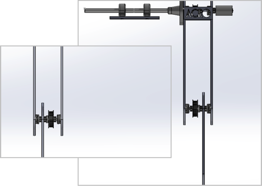
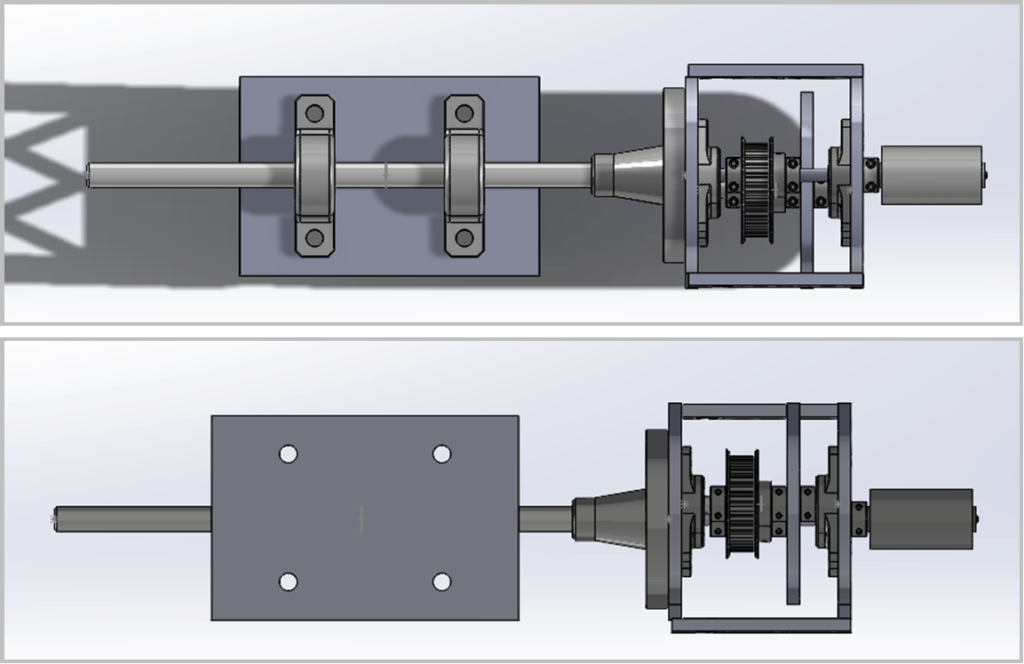
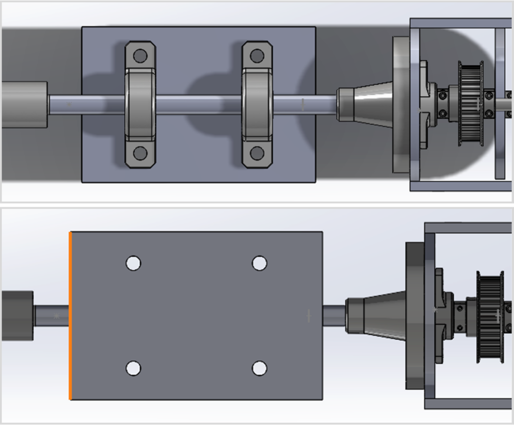
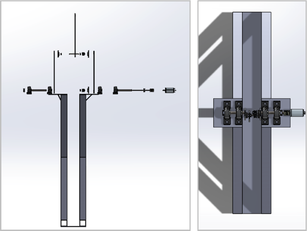
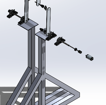
Images of our Solidworks model’s are shown later on this page as well as explanations of our belt drive and dual shear chassis design:
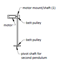
A belt drive could use either of the two linkage options and has some distinct pros and cons. Using a pulley system would reduce the amount of momentum needed to overcome for machine movement. A pulley system has the potentially lighter weight than a gear drive train. A belt system could be inexpensive to produce and easy to maintain. The cons are the potential issues with belt tensioning leading to subsequent slippage. Similarly, slippage could negatively impact the accuracy of measurements. Depending upon the construction method it may not be aesthetically pleasing and may need scheduled maintenance on a time based schedule regarding belt degradation.
Dual Shear Compact Design
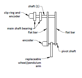
There will also be two potential linkages examined. The first is a new concept shown in figure 4. The Second is to use tubular linkage bodies, as seen in figure 1 and 5. The initial conceptual benefits include dual shear linkage subsequently increasing safety. Another benefit would be smaller stowage positions by folding in itself and ease of manufacturing. The largest potential negative aspect is increase in angular momentum dependent upon the design. It also may not be as aesthetically pleasing.
Concentric Motor Model
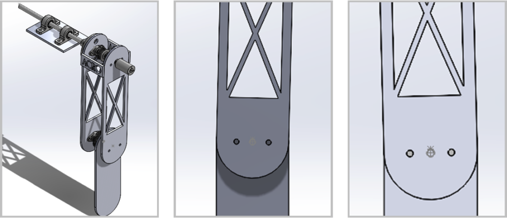

Concentric Shaft Model


Final Design
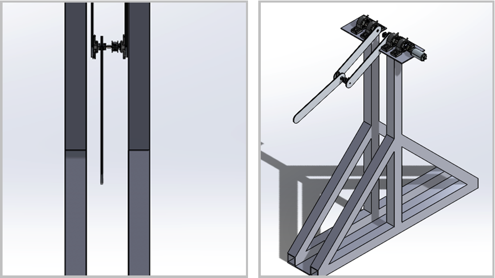
The final design is a modification of the dual shear concentric shaft design which uses a split primary shaft to allow a longer second linkage. This longer linkage will improve design performance considerably.
Testing of Performance
Most of the testing for our double pendulum will come once the product is in prototyping phase and being finally assembled. While the arm lengths will be measured before assembly, once everything is put together, the total length of the apparatus will be measured to ensure that it’s less than 70 cm. Once the double pendulum is built, it will be mounted to the table and run to check that all the pieces are properly assembled and structurally safe for the user and anyone else in the room. The device will be run twice so we can check that the pendulum will stop by switching the regular on/off switch and the emergency switch.
After the device has been fully tested to make sure that the device is safe to operate, each team member will be timed replacing the second pendulum with the wheel and then the times will be averaged to make sure that it can be switched in the time allotted for that task. This process will also be done with random parts and pieces on the double pendulum to check that each part can be easily and quickly changed or replaced if an issue is encountered. Doing this will extend the life of the product so that if something breaks, it can be replaced and fixed instead of being completely out of commission. The team will also take turns putting the fully assembled double pendulum into its stowed position and carrying it individually.
In order to make sure that the finished product is aesthetically pleasing, a picture will be taken and distributed by Gus Engstrom via email to the students in our team’s senior design class and the graduate students in Dr. Satici’s robotics lab. Each student will then be able to reply with whether or not they like the design, and if they don’t they can explain why.
In order to test the performance of the double pendulum, each individual system will be tested. For example, the drivetrain will be run apart from the entire double pendulum to ensure that the pulley system is running correctly and that the belt has the right amount of tension. This will also allow the slippage, or hopefully lack thereof, to be tested and corrected if necessary. While not required, there are other tests that will be performed once the double pendulum is completely assembled. One main test will be to see how many swings it takes for our double pendulum to vertically balance.

